The use of one static switch per module is favoured to avoid a single point of failure.
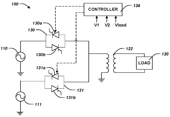
Static switch circuit diagram.
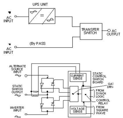
Parts of a static transfer switch.
Current flow will be through load r l s 1 r 1 and gate to mt1 junction of the thyristor.
Static transfer switch b.
When a deviation from the pre set limits on the preferred source is detected a transfer signal is generated.
A ups bypass switch is a non essential addition to an uninterruptible power supply system that while not integral to ups operation is definitely useful in the event of maintenance or repair.
Silicon controlled rectifiers of which the internal structure is made up of.
Three wire cable runs between the switches and the outlet.
When this current reaches.
3 way switched outlet wiring.
In some ups installations the transfer is delayed for a finite time to allow a load protection fuse or circuit breaker to act and clear the fault so avoiding subjecting the load to raw mains or even.
In this diagram two 3 way switches control a wall receptacle outlet that may be used to control a lamp from two entrances to a room.
The circuit operation occurs when switch s 1 is closed since the triac q 1 will initially be in the block ing condition.
Capable of providing all information concerning equipment operation status.
During the positive half cycle of the sinusoidal waveform the device is forward biased but with switch s 1 open zero gate current is applied to the thyristor and it remains.
Today s upss that use modular technology are flexible and easily scalable while protecting their critical load from many different threat types.
Sts 4p 100 400 600 a static switch is fitted with a block diagram with led indicators and a 4 line 20char display.
A breaker or a bus assembly.
Typical static switch circuit.
This circuit is wired the same way as the 3 way lights at this link.
The block diagram of a static switch is shown below.
A static power transfer switch consists of three basic parts.
Some transfer switches are manual in that an operator effects the transfer by throwing a switch while others are automatic and trigger when they sense one of the sources has lost or gained power.
The source is at the sw1 where the hot is connected to.
Static switches play a key role in assuring this resilient performance.
A transfer switch is an electrical switch that switches a load between two sources.
Together with the power source priority selection button enables operators to make full use of the apparatus.
Control system and metering system.
The core items you need in order to be protected in the event of power failure are a ups and a battery to supply the power under standard operation this should be all that is required.